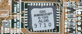
All motherboards include a small block of Read Only Memory (ROM) which is separate from the main system memory used for loading and running software. The BIOS will most likely be stored in a 32-pin chip, which can typically be identified by a silver or gold sticker that shows the name of the BIOS company – such as AMIBIOS, AWARD or Phoenix – and a code that indicates the version of code it contains. If its rectangular in shape, it’s what is known as a DIP (Dual In-line Package) chip. Older motherboards may have 28-pin DIP BIOS chips. If your BIOS chip is square with connections on all four sides, it is in a PLCC (Plastic Leaded Chip Carrier) package. A locating notch indicates the orientation of pin 1.

The ROM contains the PC’s Basic Input/Output System (BIOS). This offers two advantages: the code and data in the ROM BIOS need not be reloaded each time the computer is started, and they cannot be corrupted by wayward applications that write into the wrong part of memory. If you have a DIP or PLCC chip that’s actually soldered to your motherboard, you’ll not be able to upgrade it by replacing the ROM. Modern-day BIOSes are flash upgradeable, meaning they may be updated via a floppy disk or, sometimes, through Windows, to ensure future compatibility with new chips, add-on cards and so on.
The BIOS comprises several separate routines, serving different functions. The first part runs as soon as the machine is powered on. It inspects the computer to determine what hardware is fitted and then conducts some simple tests to check that everything is functioning normally – a process called the power-on self test (POST). If any of the peripherals are plug and play devices, it’s at this point that the BIOS assigns their resources within the system. There’s also an option to enter the Setup program, allowing the user to tell the PC what hardware is fitted. Thanks to automatic self-configuring BIOSes this isn’t used so much now, but is useful when encountering system errors, or for optimising a system setup for advanced users.
If all the tests are passed, the ROM then tries to determine which drive to boot the machine from. Older PCs ship with the BIOS set to check for the presence of an operating system in the floppy disk drive first (A:), then on the primary hard disk drive. Later PCs have more options, including boot from a CD or DVD drive, or booting from a USB device. BIOS options will allow configuring the sequence of boot devices, which can reduce normal boot time by a few seconds.
Some BIOS’s also allow booting from a hard disk drive other than the primary IDE drive. In this case it would be possible to have different operating systems – or separate instances of the same OS – on different drives. Many BIOSes allow the start-up process to be interrupted to specify the first boot device without actually having to enter the BIOS setup utility itself. If no bootable drive is detected, a message is displayed indicating that the system requires a system disk. Once the machine has booted, the BIOS serves a different purpose by presenting DOS with a standardised API for the PC hardware. In the days before Windows, this was a vital function, but 32-bit “protect mode” software doesn’t use the BIOS, so it’s of less benefit in modern PCs.
Since Windows 98, there has been operating system provision for multiple display support. Early in this development, PCs may have only a single AGP slot, so users wishing to use multiple monitors would need to install a second graphics card in a PCI slot. In such cases, most BIOSes would treat the PCI card as the main graphics card by default. Some, however, allowed either the AGP card or the PCI card to be designated as the primary graphics card. Since many graphics cards now provide two monitor outputs, this sidesteps the need for BIOS support.
Whilst the PCI and ePCI interface has helped reduce motherboard demands – by allowing IRQs to be shared more easily – the limited number of IRQ settings available to a PC remained a problem for many PC users. For this reason, most BIOSes allow ports that are not in use to be disabled. That said, with the increasing popularity of broadband Internet connections through network ports and the ever-increasing availability of peripherals that use the USB interface, serial and parallel ports have become redundant, allowing chain interfaces, such as USB, to provide support for multiple devices. In this trend the motherboard’s demands become once again the central management point, rather than the provider, of services to the computer system.
- Evolution of the motherboard
- BIOS – What motherboard BIOS does for a PC
- CMOS – complementary metal oxide silicon – RAM chips on motherboards
- EFI – Extensible Firmware Interface – explained
- Motherboard form factors
- Baby AT (BAT) Motherboard Form Factor
- LPX – Low Profile eXtension motherboard form factor
- ATX form factor
- NLX – New Low profile eXtended – form factor for motherboards
- Micro ATX motherboard form factor
- FlexATX motherboard form factor
- BTX – Balanced Technology eXtended – Motherboard Form Factor
- Riser architectures for motherboards
- CPU interfaces – motherboard slots and sockets for AMD and Intel processors