LAN switches are an expansion of the concept in LAN bridging. They operate at Layer 2 (link layer) of the OSI reference model, which controls data flow, handles transmission errors, provides physical (as opposed to logical) addressing, and manages access to the physical medium. Switches provide these functions by using various link-layer protocols – such as Ethernet, Token Ring and FDDI – that dictate specific flow control, error handling, addressing, and media-access algorithms.
LAN switches can link four, six, ten or more networks together, and have two basic architectures: cut-through and store-and-forward. In the past, cut-through switches were faster because they examined the packet destination address only before forwarding it on to its destination segment. A store-and-forward switch, on the other hand, accepts and analyses the entire packet before forwarding it to its destination.
It takes more time to examine the entire packet, but it allows the switch to catch certain packet errors and keep them from propagating through the network. By the late 1990s, the speed of store-and-forward switches had caught up with cut-through switches so the difference between the two was minimal. By then, a large number of hybrid switches had become available that mixed both cut-through and store-and-forward architectures.
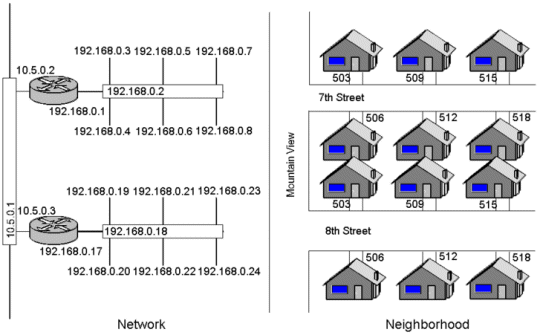
One way to think of the relative functions of routers and switches is in terms of a residential neighbourhood. The switches are analogous to the streets in the neighbourhood and the routers as the intersections with the street signs. Each house on the street has an address within a range on the block. In the same way, a switch connects various devices each with their own IP address(es) on a LAN. However, the switch knows nothing about IP addresses except its own management address. Routers connect networks together the way that major intersections connect streets to both highways and freeways, etc. The street signs at the intersection (routing table) show which way the packets need to flow.
