Dual-channel memory operation is dependent on a number of conditions being met, Intel specifying that motherboards should default to single-channel mode in the event of any of these being violated:
- DIMMs must be installed in pairs
- Both DIMMs must use the same density memory chips
- Both DIMMs must use the same DRAM bus width
- Both DIMMs must be either single-sided or dual-sided.
Currently, there are two different strategies being employed in dual-channel memory controllers, one in which where each memory bank has its own memory channel and an arbiter distributes the load between them and the other to actually create a wider memory channel, thereby doubling up on standard DDR’s 64-bit data paths. Current Intel chipsets employ the latter technique, with each pair of installed DIMMs acting as a 128-bit memory module, able to transfer twice as much data as a single-channel solution, without the need for an arbiter.

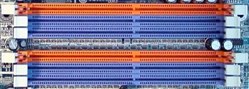
This particular motherboard has 6 DIMM slots, arranged as two groups of three and colour-coded to indicate how memory modules should be installed in pairs.
Each group represents a separate channel, as follows:
- Channel A: DIMMs 1, 2 and 3
- Channel B: DIMMs 4, 5 and 6
DIMM1 pairing up with DIMM4 (the pair of orange slots), DIMM2 with DIMM5 and DIMM3 with DIMM6.
It’s important to refer to the Motherboard User Manual to determine precisely how DIMM slots may be populated to achieve dual-channel operation. In this case, DIMM3 and DIMM6 can only be used if the neighbouring DIMM2 and DIMM5 slots are either not occupied, or occupied with only a single-sided DIMM, the following table illustrating all the permitted dual-channel combinations:
| DIMM1 | DIMM2 | DIMM3 | DIMM4 | DIMM5 | DIMM6 | |
|---|---|---|---|---|---|---|
| 2 memory modules | DS/SS | X | X | DS/SS | X | X |
| X | DS/SS | X | X | DS/SS | X | |
| X | X | DS/SS | X | X | DS/SS | |
| 4 memory modules | DS/SS | DS/SS | X | DS/SS | DS/SS | X |
| 6 memory modules | DS/SS | SS | SS | DS/SS | SS | SS |
It is also the case that dual-channel memory performance varies, dependent on the way in which memory is configured. The following table illustrates DDR400 performance for the Intel 865P chipset used by the motherboard in question:
| # DIMMS | Sides per DIMM | Mode | SC or DC | Ranking |
|---|---|---|---|---|
| 2 | 2 | Dynamic | Dual channel | 1 |
| 4 | 2 | Dynamic | Dual channel | 2 |
| 4 | 1 | Dynamic | Dual channel | 2 |
| 2 | 1 | Dynamic | Dual channel | 3 |
| 4 | Any | Normal | Dual channel | 4 |
| Any | 2 | Dynamic | Single channel | 5 |
| Any | 1 | Dynamic | Single channel | 6 |
| Any | Any | Normal | Single channel | 7 |
Interestingly, the first two rankings are reversed for the 875P chipset.
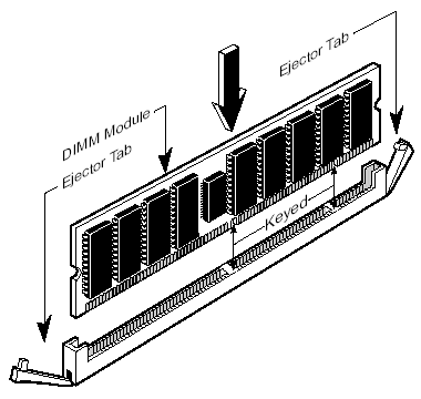
Insert the module into an available expansion socket, noting how the module is keyed to the socket. This insures the module can be plugged into the socket one way only.

SDRAM DIMMs and RIMMs both have two notches, albeit with different spacing. DDR modules – which we’re using here – have only one.
Firmly press the module into position, making certain the module is completely seated in the socket. The ejector tab clips will close automatically.
Repeat this procedure for each module you are installing.