The first thing you’re going to need to do is ensure that your system can accommodate a second hard disk drive.
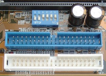
Most motherboards provide support for two IDE channels, IDE1 – the primary channel, and IDE2 – the secondary channel. Some modern-day motherboards have an additional controller, enabling them to provide four IDE channels. The connectors can be used to connect to up to four ATA devices, a master drive and a slave drive on each channel. The ATA standard has evolved over the years, with current motherboards supporting the ATA/133 standard.
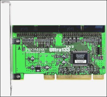
Optical drives – CD-ROM drives and CD-Writers – and other removable ATAPI devices also connect via an IDE channel, so you need to make sure there’s one free for your hard drive. If you haven’t, you can always consider installing a PCI IDE controller host adapter card. Typically, these are available in versions providing between one and four connectors.
If your second hard drive is going to have to be purchased, it’s wise to check which version of ATA your system supports before spending your hard-earned cash. It doesn’t make sense to pay a premium price for an ultra fast drive if your motherboard’s chipset isn’t capable of supporting it. As a guide ATA/33 first appeared in the second half of 1997, ATA/66 in 1999, ATA/100 in 2000 and ATA/133 a year later.
If your system dates from the 1990s, you also need to confirm that its BIOS doesn’t impose a restriction on the size of drive that can be supported that might make the upgrade not worthwhile. There have been several of these over the years.
Whilst Bill Gates’ assertion that 640KB ought to be enough for anyone is the most famous example of lack of foresight when it comes to predicting capacity requirements, it is merely symptomatic of a trait that has afflicted the PC industry since its beginnings in the early 1980s. In the field of hard disk technology at least 10 different capacity barriers occurred in the space of 15 years. Several have been the result of BIOS or operating system issues, a consequence of either short-sighted design, restrictions imposed by file systems of the day or simply as a result of bugs in hardware or software implementations. Others have been caused by limitations in the associated hard disk drive standards themselves.
IDE hard drives identify themselves to the system BIOS by the number of cylinders, heads and sectors per track. This information is then stored in the CMOS. Sectors are always 512 bytes in size. Therefore, the capacity of a drive can be determined by multiplying the number of cylinders by the number of sectors by 512. The BIOS interface allows for a maximum of 1024 cylinders, 255 heads and 63 sectors. This calculates out at 504MiB. The IEC’s binary megabyte notation was intended to address the confusion caused by the fact that this capacity is referred to as 528MB by drive manufacturers, who consider a megabyte to be 1,000,000 bytes instead of the binary programming standard of 1,048,576 bytes.
The 528MB barrier was the most infamous of all the hard disk capacity restrictions and primarily affected PCs with BIOSes created before mid-1994. It arose because of the restriction of the number of addressable cylinders to 1,024. It’s removal – which led to the E (for Enhanced) being added to the IDE specification – by abandoning the cylinders, heads and sectors (CHS) addressing technique in favour of logical block addressing, or LBA. This is also referred to as the BIOS Int13h extensions. With this system the BIOS translates the cylinder, head and sector (CHS) information into a 28-bit logical block address, allowing operating systems and applications to access much larger drives.
Unfortunately, the designers of the system BIOS and the ATA interface did not set up the total bytes used for addressing in the same manner, nor did they define the same number of bytes for the cylinder, head, and sector addressing. The differences in the CHS configurations required that there be a translation of the address when data was sent from the system (using the system BIOS) and the ATA interface. The result was that the introduction of LBA did not immediately solve the problem of the 528MB barrier and also gave rise to a further restriction at 8.4GB.
The 8.4GB barrier involved the total addressing space that was defined for the system BIOS. Prior to 1997 most PC systems were limited to accessing drives with a capacity of 8.4GB or less. The reason for this was that although the ATA interface used 28-bit addressing which supported drive capacities up to 2**28 x 512 bytes or 137GB, the BIOS Int13h standard imposed a restriction of 24-bit addressing, thereby limiting access to a maximum of only 2**24 x 512 bytes or 8.4GB.
The solution to the 8.4GB barrier was an enhancement of the Int13h standard by what is referred to as Int13h extensions. This allows for a quad-word or 64 bits of addressing, which is equal to 2**64 x 512 bytes or 9.4 x 10**21 bytes. That is 9.4 Tera Gigabytes or over a trillion times as large as an 8.4GB drive. It was not until after mid-1998 that systems were being built that properly supported the BIOS Int13h extensions.
By the beginning of the new millennium, and much to the embarrassment of the drive and BIOS manufacturers, the 137GB limit imposed by the ATA interface’s 28-bit addressing was itself beginning to look rather restrictive. However – better late than never – it appears as though the standards bodies may have finally learnt from their previous mistakes. The next version of the EIDE protocol (ATA-6), drafted in 2001, allows for 48 bits of address space, giving a maximum addressable limit of 144PB (Petabytes), hopefully sufficient for the next 20 years at least!.
You’ll need to verify that your computer has enough power supply capacity to support a second hard drive. Computers are normally built with extra power capacity, implied by the presence of spare power connectors. If you’ve already added devices to the machine, perhaps to the extent of having used all the available power connectors, it may prove necessary to upgrade your power supply unit (PSU).
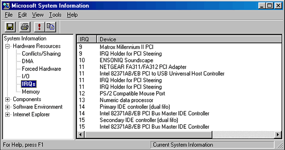
Each IDE channel will use an IRQ and I/O address as well, consuming valuable system resources; a system using multiple IDE devices may need to be carefully planned to take account of these limitations.
View these under both Windows 98 and Windows XP by selecting Start > Programs > Accessories > System Tools, double-clicking System Information and selecting IRQs and I/O respectively.
In the absence of a showstopper, you’ll need now to open up the system case and figure out where exactly you’re going to mount the new drive.
The connection between motherboard and drive is made by way of a 40-pin ribbon cable. Since the advent of ATA/100, two types of cable have existed, one having twice the number of wires as the standard type. This 80-conductor cable puts a ground pin between each control and data signal, thereby improving signal reliability. Use it if your drive/motherboard is capable of ATA/66 or later speeds.
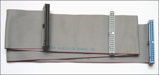
An IDE ribbon cable has three plugs – one for the motherboard, and the other two for the connected drives. These days they’re colour-coded; the blue connector goes into the motherboard, the black connector – furthermost away from the blue end – is for master drive and the grey connector – in the middle – is for the slave drive. Most cables are keyed, to prevent them being fit the wrong way round. In the absence of a key, the rule is that the red (or blue) line always goes next to pin 1.
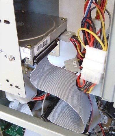
Hard drives can generate a considerable amount of heat, so ventilation is an important consideration when deciding where to locate a second hard drive. If possible, avoid mounting it in an adjacent bay and bear in mind the degree to which ribbon cables can constrain airflow.
Here, there’s plenty of space in the internal drive cage, mounted at the rear of the case. The primary/slave is the most conveniently located IDE connector. However, whether or not this is also the best to use is another question. There’s no single best way of allocating drives to IDE channels. The optimum arrangement depends very much on the nature of the drives and the way in which they’re most often used.
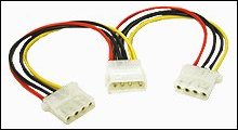
There’s also a conveniently located spare power supply plug (labelled P3). If there wasn’t, you could always a Y-style power cable splitter to turn a single power connector into two.
The power connector will fit on the four pins only one way, but they’re often a tight fit and require some force to connect them properly.
A common reason for installing a second hard drive is to use it as a backup device. If the new drive is better than your existing drive – in terms of speed and/or capacity – you may want to consider using it as your primary drive and demoting your current drive to backup duty. Often the disk utilities included with a hard drive – or available from the manufacturer’s web site – will automate the process of moving data from the old drive to the new.
In this case, the second hard drive is going to be used in a dual-boot system. Since that implies that generally only one of the two hard drives will be in use at any one time, it makes sense to allocate it to the primary/slave IDE connector.
Although a single IDE channel can handle two connected devices, it’s important to understand that these share the channel, which can only process a single request at a time. This means that when one device is active, the other is, by definition, inactive. In the event of two requests being made simultaneously, an IDE controller will give precedence to that made by the primary device. Furthermore, the chipset on some older systems will not support independent timing, with the result that both devices connected to an IDE channel will run at the speed of the slowest.
These factors need to be taken into account in determining which configuration of multiple IDE/ATA devices will maximise your overall system performance.
The most common 4-drive scenario is:
- hard drive 1
- hard drive 2
- CD-ROM drive
- CD-(Re)Writer drive
The first hard disk drive should always be configured as the primary master.
In the past, the conventional wisdom was that the way to minimise making coasters was to have the CD-ROM and CD-Writers on different channels, and to configure the CD-ROM drive as a master. For older systems this may still be an important consideration. However, it’s less relevant for more modern systems, and especially those that include a CD-Writer that supports one of the several technologies now available for avoiding buffer underruns.
On the assumption that the hard drives are likely to be the fastest devices, perhaps a more appropriate rule is to allocate these as the primary devices on each of the IDE channels unless you have a dual-boot system, in which case they should be configured as master and slave on the primary channel.
The bottom line is that there’s no one single configuration that is optimal for everyone. You simply need to figure out what arrangement will work best for you, and perhaps refine this by trial and error. In truth, the more modern your system, the less likely is that the way in which you configure your IDE channels will make an appreciable difference to performance.
Whilst you have easy access to back of both drives, you’ll need to ensure that their jumper blocks are properly configured.