A floppy disk drive’s connectors are at the back of the unit.
Controller connector:
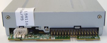
The floppy drive connector looks similar to a 40-pin IDE connector, but is a little smaller with a pin count of 34.
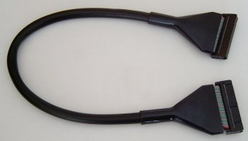
However, as with an IDE cable, the convention is for Pin 1 on the connector to correspond with the red wire of the floppy drive ribbon.
This applies with rounded floppy cables – as we’re using here – as well as the more conventional floppy ribbon cable.
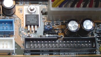
Connect the floppy drive ribbon between the drive and the the floppy drive connector on the motherboard – next to the pair of IDE controllers – making sure to similarly align the red line up with Pin 1 on the motherboard connector. These days both connectors and cables are keyed to prevent them being inserted the wrong way round.
A standard 5-connector floppy ribbon cable is a far more complex looking beast.
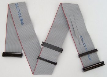
At one end is a 34-pin header connector for connection to the motherboard floppy disk controller. In the middle and at the opposite end of the cable are two pairs of connector, each comprising a 34-pin header type connector for use with a modern day 3.5in floppy drive and a larger card edge connector – used in bygone days by older 5.25in floppy disk drives.
However, it is the twist in the cable that effectively reverses the signals sent by a group of seven of the cable’s wires, immediately before the end pair of connectors, that characterises a conventional floppy drive ribbon cable.
Historically, floppy drives used a drive select (DS) jumper to configure the drive as either the A: or B: drive in the system. These days floppy drives come preconfigured as :B drives and its the floppy cable itself that determines how the system sees the drive.
A drive connected to the middle connector will be seen as it’s been configured, namely as a :B drive. However, a drive connected to the end connector will effectively have it’s drive letter designation reversed by the twist in the cable, so that it’s recognised as an :A drive.
Power connector:
The small white connector to the left of the controller connector is the drive’s power connector.
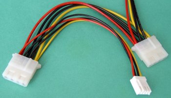
Connect this to a spare small female 4-pin white connector from the power supply.
Again, the connector and receptacle are keyed to prevent insertion the wrong way round.
- Drive Installation Terminology
- CD-RW Installation Intro
- CD-RW Installation Configuration
- CD-RW Installation Mounting
- CD-RW Installation Connection
- CD-RW Installation Bios Setup
- CD-RW Burning Software
- CD-RW Installation Optimization
- Floppy Installation Intro
- Floppy Installation Mounting
- Floppy Installation Connection
- Floppy Drive Installation BIOS Setup