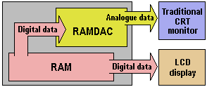
When LCD panels first emerged, they connected to a graphics card via its VGA connector. This, of course, required that the graphics card first to convert the signal to analogue via its RAMDAC. Since LCDs are – unlike CRT monitors, fundamentally digital in nature, the analogue signal is immediately reconverted to digital. The internal circuitry needed to do this increases the cost of LCD displays, impinges on image quality – particularly in the area of colour accuracy – and presents synchronisation issues that can be difficult to adjust on some graphics adapters. Whilst entirely digital LCD displays promised a better, more reliable image, they also required a new connector and internal circuitry on the graphics card.

With LCDs gaining market share at an ever quickening pace, the pressure was on graphics adapter manufacturers to produce products which allowed this, and by the late 1990s several had begun working on digital graphics card solutions – either dedicated digital, dual digital/analogue or analogue with digital add-ons. However, disagreements over the necessary standards threatened to delay progress.
In late 1997 the Video Electronics Standards Association (VESA) committee approved a new 32-pin connector called Plug and Display (P&D), which would support digital LCDs and standard CRTs, and route USB and FireWire signals through a single cable. In mid-1998, Compaq and graphics manufacturer ATI Technologies started the Digital Flat Panel (DFP) Initiative, which subsequently turned into a consortium of vendors (IBM was conspicuous by its absence) supporting a simpler 20-pin connector that only transmits digital signals and drops the USB and FireWire support. In the end, DFP’s lack of support for resolutions greater than SXGA proved to be too great a handicap, especially with the need for compatibility with emerging technologies such as HDTV, which has a resolution of 1920×1080.
In the end the standards battle appeared to be a two horse race between transition minimised differential signalling (TMDS) – also known as PanelLink – which had already been accepted by VESA as its DFP-2 standard for notebooks, and National Semiconductors’ low-voltage differential signalling (LVDS) – also used in some notebooks – which was supported by Silicon Graphics and #9, amongst others. There were advantages and disadvantages to both technologies:
- LVDS used four pairs of wires rather than three, but the technology didn’t transition well to external desktop displays.
- PanelLink didn’t support resolutions above 1280×1024 and depended on a single component manufacturer (Silicon Image) for major elements; however, it was capable of running over a cable of up to five metres, making it more suitable for remote displays.
The matter was finally resolved by the Digital Display Working Group (DDWG) – formed for the express purpose of developing a universal standard for attaching a flat-panel display to a PC. Its specification of the Digital Visual Interface (DVI) standard was published in the spring of 1999 and it was not long before graphics cards and flat-panel displays with DVI connectors began to emerge.
- How Do Computers Make Pictures?
- Graphic Card Resolution
- Graphic Card Colour Depth
- Graphic Card Components
- Graphic Card Memory
- Graphic Card Driver Software
- 3d Accelerated Graphic Cards
- Graphic Card Geometry
- 3D Rendering
- FSAA Graphic Card Technology
- Digital Graphic Cards
- DVI Graphic Cards
- HDCP Technology
- Graphic Card HDMI Ports
- Graphic Card Display Port
- Unified Display Special Interest Group
- DirectX
- OpenGL technology
- Direct3D
- Talisman
- Fahrenheit Graphic Cards
- SLI Technology
- CrossFire Graphic Cards