Most CRT monitors have case depths about as deep as the screen is wide, begging the question what is it that’s inside a monitor that requires as much space as a PC’s system case itself?
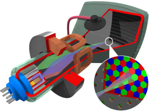
A CRT is essentially an oddly-shaped, sealed glass bottle with no air inside. It begins with a slim neck and tapers outward until it forms a large base. The base is the monitor’s screen and is coated on the inside with a matrix of thousands of tiny phosphor dots. Phosphors are chemicals which emit light when excited by a stream of electrons: different phosphors emit different coloured light. Each dot consists of three blobs of coloured phosphor: one red, one green, one blue. These groups of three phosphors make up what is known as a single pixel.

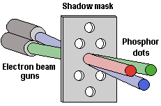
In the bottle neck of the CRT is the electron gun, which is composed of a cathode, heat source and focusing elements. Colour monitors have three separate electron guns, one for each phosphor colour. Images are created when electrons, fired from the electron guns, converge to strike their respective phosphor blobs.
Convergence is the ability of the three electron beams to come together at a single spot on the surface of the CRT. Precise convergence is necessary as CRT displays work on the principal of additive coloration, whereby combination of different intensities of red green and blue phosphors create the illusion of millions of colours. When each of the primary colours are added in equal amounts they will form a white spot, while the absence of any colour creates a black spot. Misconvergence shows up as shadows which appear around text and graphic images.
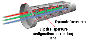
The electron gun radiates electrons when the heater is hot enough to liberate electrons (negatively charged) from the cathode. In order for the electrons to reach the phosphor, they have first to pass through the monitor’s focusing elements. While the radiated electron beam will be circular in the middle of the screen, it has a tendency to become elliptical as it spreads its outer areas, creating a distorted image in a process referred to as astigmatism. The focusing elements are set up in such a way as to initially focus the electron flow into a very thin beam and then – having corrected for astigmatism – in a specific direction. This is how the electron beam lights up a specific phosphor dot, the electrons being drawn toward the phosphor dots by a powerful, positively charged anode, located near the screen.

The deflection yoke around the neck of the CRT creates a magnetic field which controls the direction of the electron beams, guiding them to strike the proper position on the screen. This starts in the top left corner (as viewed from the front) and flashes on and off as it moves across the row, or raster, from left to right. When it reaches the edge of the screen, it stops and moves down to the next line. Its motion from right to left is called horizontal retrace and is timed to coincide with the horizontal blanking interval so that the retrace lines will be invisible. The beam repeats this process until all lines on the screen are traced, at which point it moves from the bottom to the top of the screen – during the vertical retrace interval – ready to display the next screen image.
Since the surface of a CRT is not truly spherical, the beams which have to travel to the centre of the display are foreshortened, while those that travel to the corners of the display are comparatively longer. This means that the period of time beams are subjected to magnetic deflection varies, according to their direction. To compensate, CRT’s have a deflection circuit which dynamically varies the deflection current depending on the position that the electron beam should strike the CRT surface.
Before the electron beam strikes the phosphor dots, it travels thorough a perforated sheet located directly in front of the phosphor. Originally known as a shadow mask, these sheets are now available in a number of forms, designed to suit the various CRT tube technologies that have emerged over the years. They perform a number of important functions:
- they mask the electron beam, forming a smaller, more rounded point that can strike individual phosphor dots cleanly
- they filter out stray electrons, thereby minimising overspill and ensuring that only the intended phosphors are hit
- by guiding the electrons to the correct phosphor colours, they permit independent control of brightness of the monitor’s three primary colours.

When the beam impinges on the front of the screen, the energetic electrons collide with the phosphors that correlate to the pixels of the image that’s to be created on the screen. When this happens each is illuminated, to a greater or lesser extent, and light is emitted in the colour of the individual phosphor blobs. Their proximity causes the human eye to perceive the combination as a single coloured pixel.
- Flat Panel & LCD Monitors
- The Anatomy of a CRT Monitor (and CRT TVs)
- CRT Monitor Resolution and Refresh Rates (VSF)
- Monitor Interlacing
- What is the Dot Pitch of a Computer Monitor
- Dot Trio Monitors
- Grill Aperture Monitors
- Monitor Technologies: Slotted Mask
- Enhanced Dot Pitch Monitors
- Electron Beam Monitors
- Monitor Controls
- The Different Types of CRT Monitors – From ShortNeck to FST
- What is a Digital CRT Monitor and How Does It Work
- What is LightFrame Technology?
- Safety Standards For Computer Monitors
- TCO Monitor Standards
- Monitor Ergonomics