Communication channels like telephone lines are usually analogue media. Analogue media is a bandwidth limited channel. In the case of telephone lines the usable bandwidth frequencies is in the range of 300 Hz to 3300 Hz.
Data communication means moving digital information from one place to another through communication channels. These digital information signals have the shape of square waves and the meaning of 0 and 1.

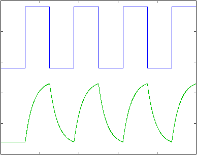
If such digital signals were transmitted on analogue media the square waves of the digital signals would be distorted by the analogue media. The receiver which receives these distorted signals will be unable to interpret accurately the incoming signals. The solution is to convert these digital signals into analogue signals so that the communication channels can carry the information from one place to another reliably. The technique which enables this conversion is called modulation.
Modulation is a technique of modifying some basic analogue signal in a known way in order to encode information in that basic signal. Any measurable property of an analogue signal can be used to transmit information by changing this property in some known manner and then detecting those changes at the receiver end. The signal that is modulated is called the carrier signal, because it carries the digital information from one end of the communication channel to the other end.
The device that changes the signal at the transmitting end of the communication channel is called the modulator. The device at the receiving end of the channel, which detects the digital information from the modulated signal, is called the demodulator.
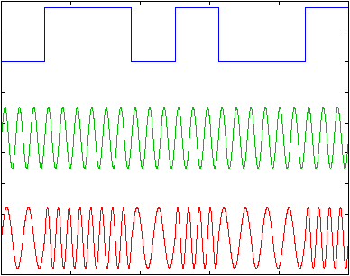
With Frequency Modulation, the frequency of the carrier signal is changed according to the data. The transmitter sends different frequencies for a 1 than for a 0. This technique is also called FSK – frequency shift keying. Its disadvantages are that the rate of frequency changes is limited by the bandwidth of the line, and that distortion caused by the lines makes the detection even harder than amplitude modulation. Today this technique is used in low rate asynchronous modems up to 1200 baud only.

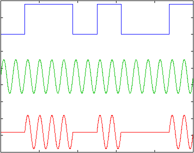
The Amplitude Modulation (AM) technique changes the amplitude of the sine wave. In the earliest modems, digital signals were converted to analogue by transmitting a large amplitude sine wave for a 1 and zero amplitude for a 0, as shown in the figure. The main advantage of this technique is that it is easy to produce such signals and also to detect them.

However, the technique has two major disadvantages. The first is that the speed of the changing amplitude is limited by the bandwidth of the line. The second is that the small amplitude changes suffer from unreliable detection. Telephone lines limit amplitude changes to some 3000 changes per second. The disadvantages of amplitude modulation causes this technique to no longer be used by modems, however, it is used in conjunction with other techniques.
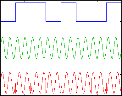
Phase Modulation (PM) is a process where two sinusoidal waveforms are compared with each other. The case where the two waveforms are going in the same direction at the same time is known as zero phase shift. With a phase shift of 180 degrees (as illustrated), waveform B starts at the mid-point of waveform A, so that when waveform A is positive waveform B is negative, and vice versa. Two phase states allow the representation of a single bit of digital data, which can have the value 0 or 1. Additional 90- and 270 degree phase shifts provide four phase shift states and the capability to represent four digital data representations.

This technique, in order to detect the phase of each symbol, requires phase synchronisation between the receiver’s and transmitter’s phase. This complicates the receiver’s design.
A sub method of the phase modulation is differential phase modulation. In this method, the modem shifts the phase of each succeeding signal in a certain number of degrees for a 0 (90 degrees for example) and a different certain number of degrees for a 1 (270 degrees for example ) – as illustrated. This method is easier to detect than the previous one. The receiver has to detect the phase shifts between symbols and not the absolute phase.

This technique is also called phase shift keying (PSK). In the case of two possible phase shifts the modulation will be called BPSK – binary PSK. In the case of 4 different phase shifts possibilities for each symbol which means that each symbol represents 2 bits the modulation will be called QPSK, and in case of 8 different phase shifts the modulation technique will be called 8PSK.
Quadrature Amplitude Modulation (QAM) allows the transmission of data using both the phase shift of PM and the signal magnitude of AM at the same time. The more phase shifts and magnitude levels used, the more data the technique can be used to transmit. However, multibit technology eventually runs out of steam. As the number of tones and phases increases, the more difficult it becomes to differentiate between similar combinations.
The PSTN was designed for voice communications – by artificially limiting the sound spectrum to just those frequencies relevant to human speech, network engineers found they could reduce the bandwidth needed per call – and while this works well for voice, it imposes limits on data communications. According to Shannon’s Law, the limitations of the PSTN impose a maximum theoretical data transmission limit of 35 Kbit/s for a wholly analogue-based connection.