Also widely referred to as FireWire, IEEE 1394 was approved by the Institute of Electrical and Electronics Engineers (IEEE) in 1995. Originally conceived by Apple, who currently receives $1 royalty per port, several leading IT companies – including Microsoft, Philips, National Semiconductor and Texas Instruments – have since joined the 1394 Trade Association.
IEEE 1394 is similar to the first version of USB in many ways, but much faster. Both are hot-swappable serial interfaces, but IEEE 1394 provides high-bandwidth, high-speed data transfers significantly in excess of what USB offers. There are two levels of interface in IEEE 1394, one for the backplane bus within the computer and another for the point-to-point interface between device and computer on the serial cable. A simple bridge connects the two environments. The backplane bus supports data-transfer speeds of 12.5, 25, or 50 Mbit/s, the cable interface speeds of 100, 200 and 400 Mbit/s – roughly four times as fast as a 100BaseT Ethernet connection and far faster than USB’s 1.5 Mbit/s or 12 Mbit/s speeds. A 1394b specification aims to adopt a different coding and data-transfer scheme that will scale to 800 Mbit/s, 1.6 Gbit/s and beyond. Its high-speed capability makes IEEE 1394 viable for connecting digital cameras, camcorders, printers, TVs, network cards and mass storage devices to a PC.
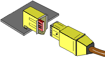
IEEE 1394 cable connectors are constructed with the electrical contacts inside the structure of the connector thus preventing any shock to the user or contamination to the contacts by the user’s hands. These connectors are derived from the Nintendo GameBoy connector. Field tested by children of all ages, this small and flexible connector is very durable. These connectors are easy to use even when the user must blindly insert them into the back of machines. There are no terminators required, or manual IDs to be set.

IEEE 1394 uses a six-conductor cable (up to 4.5 metres long) which contains two pairs of wires for data transport, and one pair for device power. The design resembles a standard 10BaseT Ethernet cable. Each signal pair is shielded and the entire cable is shielded. Cable power is specified to be from 8V dc to 40Vdc at up to 1.5 amps and is used to maintain a device’s physical layer continuity when the device is powered down or malfunctioned – a unique and very important feature for a serial topology – and provide power for devices connected to the bus. As the standard evolves, new cable designs are expected to allow longer distances without repeaters and with more bandwidth.

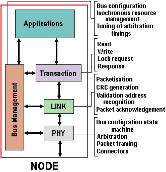
At the heart of any IEEE 1394 connection is a physical layer and a link layer semiconductor chip, and IEEE 1394 needs two chips per device. The physical interface (PHY) is a mixed signal device that connects to the other device’s PHY. It includes the logic needed to perform arbitration and bus initialisation functions. The Link interface connects the PHY and the device internals. It transmits and receives 1394-formatted data packets and supports asynchronous or isochronous data transfers. Providing both asynchronous and isochronous formats on the same interface allows both non-real-time critical applications, such as printers and scanners, and real-time critical applications, such as video and audio, to operate on the same bus. All PHY chips use the same technology, whereas the Link is device-specific. This approach allows IEEE 1394 to act as a peer-to-peer system as opposed to USB’s client-server design. As a consequence, an IEEE 1394 system needs neither a serving host, nor a PC.

Asynchronous transport is the traditional method of transmitting data between computers and peripherals, data being sent in one direction followed by acknowledgement to the requester. Asynchronous data transfers place emphasis on delivery rather than timing. The data transmission is guaranteed, and retries are supported. Isochronous data transfer ensures that data flows at a pre-set rate so that an application can handle it in a timed way. This is especially important for time-critical multimedia data where just-in-time delivery eliminates the need for costly buffering. Isochronous data transfers operate in a broadcast manner, where one or many 1394 devices can listen to the data being transmitted. Multiple channels (up to 63) of isochronous data can be transferred simultaneously on the 1394 bus. Since isochronous transfers can only take up a maximum of 80 percent of the 1394 bus bandwidth, there is enough bandwidth left over for additional asynchronous transfers.
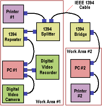
IEEE 1394’s scaleable architecture and flexible peer-to-peer topology make it ideal for connecting high-speed devices: everything from computers and hard drives, to digital audio and video hardware. Devices can be connected to in either a daisy-chain or tree topology. The diagram depicts two separate work areas connected with a 1394 bridge. Work area #1 comprises a video camera, PC, and video recorder, all interconnected via IEEE 1394. The PC is also connected to a physically distant printer via a 1394 repeater, which extends the inter-device distance by redriving the 1394 signals. Up to sixteen hops may be made between any two devices on a 1394 bus. A 1394 splitter is used between the bridge and the printer to provide another port to attach a 1394 bus bridge. Splitters provide more topology flexibility for users.

Work area #2 contains only a PC and printer on a 1394 bus segment, plus a connection to the bus bridge. The 1394 bus bridge isolates data traffic within each work area. IEEE 1394 bus bridges allow selected data to be passed from one bus segment to another. Therefore PC #2 can request image data from the video recorder in work area #1. Since the 1394 cable is powered, the PHY signalling interface is always powered, and video data is transported even if PC #1 is powered off.
Each IEEE 1394 bus segment may have up to 63 devices attached to it. Currently each device may be up to 4.5 metres apart; longer distances are possible with and without repeater hardware. Improvements to the current cabling are being specified to allow longer distance cables. Over 1000 bus segments may be connected by bridges thus providing a large growth potential. An additional feature is the ability of transactions at different speeds to occur on a single device medium. For example, some devices can communicate at 100 Mbit/s while others communicate at 200 Mbit/s and 400 Mbit/s. IEEE 1394 devices may be hot-plugged – added to or removed from the bus – even with the bus in full operation. Upon altering the bus configuration, topology changes are automatically recognised. This plug and play feature eliminates the need for address switches or other user intervention to reconfigure the bus.
As a transaction-based packet technology, 1394 can be organised as if it were memory space interconnected between devices, or as if devices resided in slots on the main backplane. Device addressing is 64 bits wide, partitioned as 10 bits for network Ids, 6 bits for node Ids and 48 bits for memory addresses. The result is the capability to address 1023 networks of 63 nodes, each with 281TB of memory. Memory-based addressing, rather than channel addressing, views resources as registers or memory that can be accessed with processor-to-memory transactions. Fundamentally, all this means easy networking – for example, a digital camera can easily send pictures directly to a digital printer without a computer in the middle – and with IEEE 1394 it is easy to see how the PC could lose its position of dominance in the interconnectivity environment and be relegated to being no more than a very intelligent peer.
The need for two pieces of silicon instead of one will make IEEE 1394 peripherals more expensive than, say, SCSI, IDE or USB devices. Consequently it is inappropriate for low speed peripherals. However, its applicability to higher-end applications, such as digital video editing, is obvious and its clear that the standard is destined to become a mainstream consumer electronics interface – used for connecting handy-cams and VCRs, set-top boxes and televisions. To date, however, its implementation has been largely confined to digital camcorders, where is it known as iLink.
In 1997, Compaq, Intel and Microsoft proposed an industry standard called Device Bay. By combining the fast interface of IEEE 1394 with the USB interface, Device Bay offered a bay slot to slide in peripherals such as hard disks or DVD-ROM players. The following year, however, proved to be a somewhat troubled year for IEEE 1394, with Apple’s announcement of what many believed to be exorbitant royalty claims for use of the technology deterring many semiconductor companies who had hitherto embraced the standard. Notwithstanding these issues – and largely because of its support of isochronous data transfer – by the start of the new millennium FireWire had established itself as the favoured technology in the area of video capture.
Indeed, its use as a hard disk interface offers a number of advantages over SCSI. Whilst its maximum data transfer speed of 400 Mbit/s (equivalent to 50 MBps) isn’t as fast as the Ultra160 SCSI standard, FireWire beats SCSI hands down when it comes to ease of installation. Where SCSI devices require a pre-assigned ID and both ends of the bus to be terminated, IEEE 1394 will dynamically assign addresses on the fly and does not require terminators. Like USB, FireWire devices are also hot-swappable, without the need to power down the PC during installation. Combined with its lack of previous stumbling blocks such as the assignment of IRQs or DMAs – these characteristics make IEEE 1394 perfect for trouble-free plug and play installations.
Despite all this, and the prospect of a number of motherboard manufacturers producing boards with built-in IEEE 1394 controllers in the second half of 2000, FireWire’s future success was far from assured – the announcement of the proposed USB 2.0 specification at the Intel Developer Forum (IDF) of February 1999 serving to significantly complicate the picture.
- What Is The System Bus?
- ISA Bus – Industry Standard Architecture
- Local Bus Interfaces
- PCI Bus Interfaces
- What is AGP and AGP Pro?
- Internal Interfaces Summary
- PCI-X Interfaces
- PCI Express Interfaces
- IDE Interfaces
- EIDE Interfaces
- Hard Disks – What IS ATA and Ultra ATA?
- Serial ATA (SATA) interface guide
- SCSI Explained – With Pictures
- SCSI Interface Evolution
- Fibre Channel Interfaces
- Hard Disks – What is Serial Storage Architecture?
- I/O Interface Standards
- How It Works: The Idea and Technology Behind USB
- IEEE 1394 Interfaces
- USB 2.0 Intefaces
- FireWire 800 Interfaces