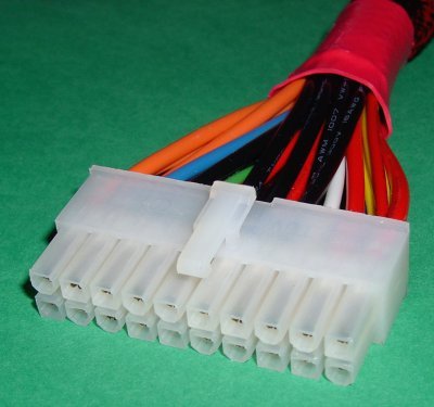
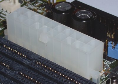
Power supply units can have up to three power connectors:
- a 20-pin main power connector; the standard ATX power connector.
- a 4-pin +12V power connector; required for all Pentium 4 processor-based systems.
- a 6-pin AUX power connector; recommended by V2.03 of the ATX Specification for motherboard’s requiring 250W or 300W supplies.
The ATX/ATX12V Power Supply Design Guide (Version 1.2) provides design suggestions and reference specifications for a family of power supplies that comply with the ATX Specification (Version 2.03) for motherboards and chassis. It describes the new superset of the original ATX power supply – named ATX12V – as comprising a standard ATX unit plus the following enhancements:
- Increased +12 VDC output capability: Motherboard components with unique voltage requirements are increasingly expected to be powered via DC/DC converters off the +12 VDC power supply output. This trend is due primarily to the higher power conversion and transmission efficiencies of +12 VDC relative to +5 VDC or +3.3 VDC. ATX12V power supplies should be designed to accommodate these increased +12 VDC current requirements and to address associated issues such as cross-regulation, capacitive loading, transient surge tolerance, cable voltage drop and cooling.
- Power Connectors: To enable the delivery of more +12 VDC current to the motherboard, a new 4-pin receptacle/header combination – the +12 V power connector – has been defined. The presence of the +12 V power connector indicates that a power supply is ATX12V; the absence of the +12 V power connector indicates that a supply is ATX. To allow for greater than 3.3 V current, the AUX Power Connector is recommended for ATX and ATX12V power supplies with 3.3 V current greater than 18 A.
ATX12V power supplies are intended to be downward compatible with ATX power supplies. Consequently, it is required that an ATX12V power supply be able to provide the same typical +5 VDC and +3.3 VDC maximum continuous output currents as an ATX supply of the same total output power.
If your motherboard doesn’t support either the 4-pin +12V connector or 6-pin AUX power connector, no problem, simply connect the standard 20-pin power connector.

The connector has a latch to ensure both proper connection and correct orientation.

Line up the connector so that all pins are properly aligned and push it firmly into the motherboard ATX power socket so that the latch clips securely to the motherboard ATX power socket.
The Intel Front Panel Connectivity Guide seeks to aid system integrators in general – and the likes of motherboard, power supply and chassis manufacturers in particular – by describing connection and mechanical recommendations for all motherboards having internal connectors requiring external connection, and by so doing establishing some degree of standardisation in the area.
All of the following aspects of V1.0 (October 2000) of the guide are covered, even though the particular motherboard and system case used in the tutorial support only a subset of these features:
- front panel switch/LED connectors
- audio connectors
- USB connectors, and
- IEEE-1394 connectors.
- Motherboard Upgrade Reasons
- Motherboard Removal
- Motherboard CPU
- Motherboard Heatsinks
- Motherboard Memory Identification
- Motherboard Memory Installation
- Motherboard Fit
- Motherboard Power
- Motherboard Panel
- Motherboard Fan
- Motherboard USB Ports
- Motherboard FireWire Ports
- Motherboard Audio
- Motherboard Testing
- Motherboard Floppy Connections
- Motherboard IDE Connections
- BIOS Settings
- Motherboards and Win98
- Motherboards and WinXP