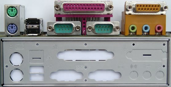
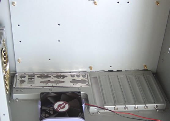
The first thing you need to do is compare the I/O shield on the system case with your motherboard’s I/O ports, both to check how well these match up and to identify any cutouts that need to be punched out.

In this case, the cutout to allow access to the game and audio ports need to be punched out.
Remove the I/O shield by applying pressure from the outside of the case in until it snaps out. This can sometimes require quite a bit of force to accomplish!
The I/O shield is typically a thin sheet of aluminium. It’s thickness varies, with more expensive cases tending to have sturdier shields. You’ll generally need a hammer and a tool like a hole punch or screwdriver to knock a cutout out. Aim for the small areas where the cutout is attached to the rest of sheet by a thicker bit of metal.
Offer the motherboard up to the replaced I/O shield to see how well its going to mate with the board’s I/O ports and mounting holes. You may find you need to remove the flashing – small strips of metal still attached to the shield where cutouts have been removed – to get thing to fit properly. Generally, game, serial and parallel ports will protrude though the shield, while USB, FireWire and audio ports remain slightly behind slightly behind it.

Whilst this system case appears to have mounting holes to accommodate a number of motherboard form factors, only those for ATX-style boards already have standoffs – typically pieces of brass that hold the motherboard up off of surface of the case – fit. Make sure that each motherboard mounting hole has a corresponding standoff and that they all line up at once. Fix additional standoffs as necessary and remove any redundant ones.
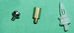
Most cases use coarse threaded screws for mounting the motherboard. Make sure they’re the right size and tighten down properly. When screwing them down make sure none come into contact with any solder or circuit trace. This is unlikely to be the case, since modern-day motherboards have insulators around their mounting holes. However, if you’re using an older board you may need to use a plastic washer or electrical tape to avoid any unwanted electrical contact.
Having screwed the motherboard into place, you’re now ready to start making the various connections to the system case and fans.
There are two types of motherboard standoff. The type most commonly used today is brass. It has threads at one end that allow it to be screwed into the system case. It has a threaded hole at the other end into which a mounting screw may be screwed.

The other type is plastic. They’re more difficult to use than the brass type, particularly when removing a board that’s going to be upgraded. Fortunately they’re used less frequently these days, modern-day motherboards having insulated mounting holes.
- Motherboard Upgrade Reasons
- Motherboard Removal
- Motherboard CPU
- Motherboard Heatsinks
- Motherboard Memory Identification
- Motherboard Memory Installation
- Motherboard Fit
- Motherboard Power
- Motherboard Panel
- Motherboard Fan
- Motherboard USB Ports
- Motherboard FireWire Ports
- Motherboard Audio
- Motherboard Testing
- Motherboard Floppy Connections
- Motherboard IDE Connections
- BIOS Settings
- Motherboards and Win98
- Motherboards and WinXP