pctechguide.com

  • Home
  • Guides
  • Tutorials
  • Articles
  • Reviews
  • Glossary
  • Contact

Floppy Installation Connection

A floppy disk drive’s connectors are at the back of the unit.

Controller connector:

Floppy

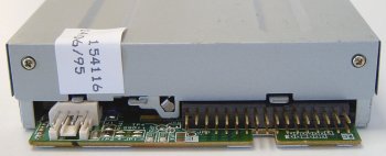
The floppy drive connector looks similar to a 40-pin IDE connector, but is a little smaller with a pin count of 34.

Round

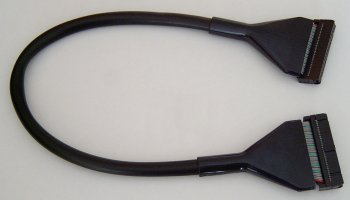
However, as with an IDE cable, the convention is for Pin 1 on the connector to correspond with the red wire of the floppy drive ribbon.


This applies with rounded floppy cables – as we’re using here – as well as the more conventional floppy ribbon cable.

Motherboard

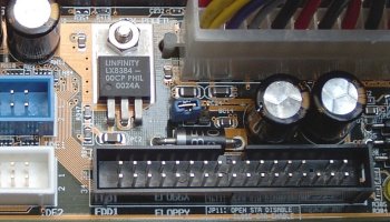
Connect the floppy drive ribbon between the drive and the the floppy drive connector on the motherboard – next to the pair of IDE controllers – making sure to similarly align the red line up with Pin 1 on the motherboard connector. These days both connectors and cables are keyed to prevent them being inserted the wrong way round.


A standard 5-connector floppy ribbon cable is a far more complex looking beast.

Floppy

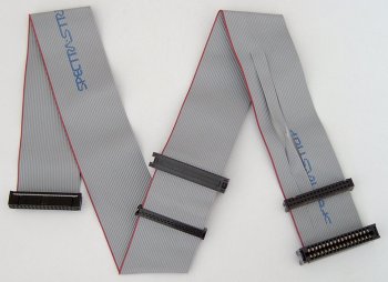
At one end is a 34-pin header connector for connection to the motherboard floppy disk controller. In the middle and at the opposite end of the cable are two pairs of connector, each comprising a 34-pin header type connector for use with a modern day 3.5in floppy drive and a larger card edge connector – used in bygone days by older 5.25in floppy disk drives.


However, it is the twist in the cable that effectively reverses the signals sent by a group of seven of the cable’s wires, immediately before the end pair of connectors, that characterises a conventional floppy drive ribbon cable.

Historically, floppy drives used a drive select (DS) jumper to configure the drive as either the A: or B: drive in the system. These days floppy drives come preconfigured as :B drives and its the floppy cable itself that determines how the system sees the drive.

A drive connected to the middle connector will be seen as it’s been configured, namely as a :B drive. However, a drive connected to the end connector will effectively have it’s drive letter designation reversed by the twist in the cable, so that it’s recognised as an :A drive.

Power connector:

The small white connector to the left of the controller connector is the drive’s power connector.

Power

Connect this to a spare small female 4-pin white connector from the power supply.

Again, the connector and receptacle are keyed to prevent insertion the wrong way round.

  • Drive Installation Terminology
  • CD-RW Installation Intro
  • CD-RW Installation Configuration
  • CD-RW Installation Mounting
  • CD-RW Installation Connection
  • CD-RW Installation Bios Setup
  • CD-RW Burning Software
  • CD-RW Installation Optimization
  • Floppy Installation Intro
  • Floppy Installation Mounting
  • Floppy Installation Connection
  • Floppy Drive Installation BIOS Setup

Filed Under: How to Install a Front Loading Drive

Latest Articles

lexmark-pro715

Lexmark Pro715

The Lexmark Pro715 MultiFunction Printer can print 10 black pages per minute and 6 color pages per minute. With a high DPI of 4800 X 1200 and scan capabilities of 1200x 1200 dpi it's clear that the Lexmark Pro715 can squeeze out a very nice picture. This is a all in one thermal inkjet printer. It … [Read More...]

Portable Music Players

Portable Music Players There are also many portable digital music players now on the market, epitomised (arguably) by the Apple iPod. Being a committed early adopter, I bought the first generation 10GB iPod, which I sold and upgraded to the 20GB model when I (quickly) exceeded 10GB of MP3 … [Read More...]

Win98 Installation Drive Formating

With the Fdisk procedure completed, restart you computer with the Windows 98 Startup disk in the floppy disk drive and proceed to format the partitions you've created with a file system, using the Format tool as follows: When the Windows 98 Startup menu is displayed, choose the Start computer … [Read More...]

Everything You Need to Know About Sourcing Circuit Boards From U.S. Suppliers

In This Article This article includes: Why Source PCBs From the United States?How to Get a Quote From a U.S.-Based PCB ManufacturerThe Top U.S. … [Read More...]

Top Taplio Alternatives in 2025 : Why MagicPost Leads for LinkedIn Posting ?

LinkedIn has become a strong platform for professionals, creators, and businesses to establish authority, grow networks, and elicit engagement. Simple … [Read More...]

Shocking Cybercrime Statistics for 2025

People all over the world are becoming more concerned about cybercrime than ever. We have recently collected some statistics on this topic and … [Read More...]

Gaming Laptop Security Guide: Protecting Your High-End Hardware Investment in 2025

Since Jacob took over PC Tech Guide, we’ve looked at how tech intersects with personal well-being and digital safety. Gaming laptops are now … [Read More...]

20 Cool Creative Commons Photographs About the Future of AI

AI technology is starting to have a huge impact on our lives. The market value for AI is estimated to have been worth $279.22 billion in 2024 and it … [Read More...]

13 Impressive Stats on the Future of AI

AI technology is starting to become much more important in our everyday lives. Many businesses are using it as well. While he has created a lot of … [Read More...]

Guides

  • Computer Communications
  • Mobile Computing
  • PC Components
  • PC Data Storage
  • PC Input-Output
  • PC Multimedia
  • Processors (CPUs)

Recent Posts

Virtual Memory

Video Covering Virtual Memory - Part of our Fix Slow Computer tutorial found on  … [Read More...]

Bitdefender Internet Security Review

[starreviewmulti id=7 tpl=20] PROS: Allows parents to put control on internet options available to their children. CONS: Takes awhile to set up, … [Read More...]

UMTS

UMTS Definition: Universal Mobile Telecommunications System: a 3G standard, being developed under the auspices of ETSI, and intended mainly for the … [Read More...]

[footer_backtotop]

Copyright © 2026 About | Privacy | Contact Information | Wrtie For Us | Disclaimer | Copyright License | Authors