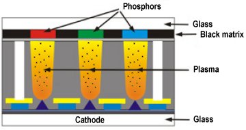
Some believe FED (field emission display) technology will be the biggest threat to LCD’s dominance in the panel display arena. FEDs capitalise on the well-established cathode-anode-phosphor technology built into full-sized CRTs using this in combination with the dot matrix cellular construction of LCDs. Instead of using a single bulky tube, FEDs use tiny mini tubes for each pixel, and the display can be built in approximately the same size as an LCD screen.
Each red, green and blue sub-pixel is effectively a miniature vacuum tube. Where the CRT uses a single gun for all pixels, a FED pixel cell has thousands of sharp cathode points, or nanocones, at its rear. These are made from material such as molybdenum, from which electrons can be pulled very easily by a voltage difference, to strike red, green and blue phosphors at the front of the cell. Colour is displayed by field sequential colour. The display will show all the green information first, then redraw the screen with red followed by blue.

In a number of areas, FEDs look to have LCDs beaten. Since FEDs produce light only from the on pixels, power consumption is dependent on the display content. This is an improvement over LCDs, where all light is created by a backlight which is always on, regardless of the actual image on the screen. The LCD’s backlight itself is a problem the FED doesn’t have. Light from the backlight of an LCD passes through to the front of the display, through the liquid crystal matrix. It’s transmissive, and the distance of the backlight to the front contributes to the narrow viewing angle. In contrast, an FED generates light from the front of the pixel, so the viewing angle is excellent – 160 degrees both vertically and horizontally.
FEDs also have redundancy built into their design, most designs using thousands of electron emitters for each pixel. Whereas one failed transistor can cause a permanently on or off pixel on an LCD, FED manufacturers claim that FEDs suffer no loss of brightness even if 20% of the emitters fail. These factors, coupled with faster than TFT LCD response times and colour reproduction equal to the CRT, make FEDs look a very promising option.
FEDs have their downsides though. One is that they are difficult to mass produce. While a CRT has just one vacuum tube, a SVGA FED needs 480,000 of them. To withstand the differences between the vacuum and external air pressure, a FED must be mechanically strong and very well sealed. Another problem is efficiency. To get enough electrons to produce adequate light, internal destruction of the emission layer is unavoidable. This begins with burn-in effects and eventually progresses to complete breakdown of the structure.
By the late 1990s, six-inch colour FED panels had already been manufactured, and research and development on 10-inch FEDs was proceeding apace. However, since then the aforementioned barriershave caused the demise of many FED efforts. Variants of the technology still appear from time to time because as many companies continue to strive for new ways to compete with LCDs.
- VA – Vertically Aligned LCD Monitors
- What in the LCD is IPS!?
- ThinCRT Flat Panels
- TFT LCD Monitors
- LCD Resolutions and Picture Scaling
- Liquid Crystal Light Polarisation in LCD Monitors
- Polysilicon Flat Panels
- Plasma Flat Panels
- PALCD Flat Panels
- OLED Flat Panels
- MVA – Multi-domain Vertical Alignment in LCD Monitors
- LEP Flat Panels
- LED Flat Panels
- LCD – Liquid Crystal Displays
- IPS – In-Plane Switching LCD Monitors
- HAD Flat Panels
- Flat Panel Feature Comparisons
- FED Flat Panels
- Digital Flat Panels
- DSTN LCD monitors
- Creating Colour in LCD Displays
- Flat Panel ALiS Technology